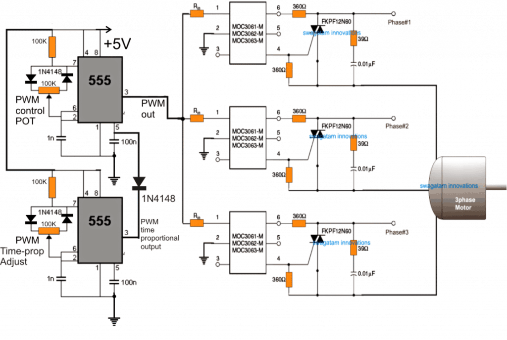
Three-phase Motor Control Circuit Diagram

Three-phase motor control circuit diagram
Speed Control of Three Phase Induction Motor
<ol class="X5LH0c"><li class="TrT0Xe">V / f control or frequency control.</li><li class="TrT0Xe">Changing the number of stator poles.</li><li class="TrT0Xe">Controlling supply voltage.</li><li class="TrT0Xe">Adding rheostat in the stator circuit.</li></ol>What is 3-phase motor circuit?
Three-phase power is a three-wire ac power circuit with each phase ac signal 120 electrical degrees apart.
What does a motor control circuit do?
The Control Circuit often operates at a lower voltage than the Power Circuit for safety and ease of installation. A device that controls the flow of electrical power to a motor. It is designed to safely start and stop a motor, and provide overload protection.
How do you check continuity on a 3-phase motor?
Using a multimeter, check the continuity of motor winding from phase to phase ( U to V, V to W , W to U ). Each phase to phase must have a continuity if winding is OK. If any particular phase fails the continuity test, your motor is probably burnt.
What are 3 types of motor controls?
There are four basic motor controller and drive types: AC, DC, servo, and stepper, each having an input power type modified to the desired output function to match with an application.
Can a PLC control a 3-phase motor?
Programmable logic controllers (PLCs) support digital input/output very effectively. So a PLC can also be used to control the operation of a VFD, hence to finally control the connected 3 Phase Induction Motor.
Why there is no neutral in 3-phase?
In single-phase, loads the neutral wire provides the return path for the current, and in balanced 3 phase loads, because they satisfy the above criteria, the currents enter and return through lines creating 0A of out of balance current. So, there is no need for a neutral wire.
What are the 3 types of 3-phase motors?
Three-phase AC motors can be divided into three general types: squirrel-cage, wound-rotor and synchronous. Only the squirrel-cage rotor motors and the wound-rotor motors are induction motors.
Why does 3-phase need a neutral?
A neutral wire allows the three phase system to use a higher voltage while still supporting lower voltage single phase appliances. In high voltage distribution situations it is common not to have a neutral wire as the loads can simply be connected between phases (phase-phase connection).
What are the components of motor control circuit?
The control circuit consists of components of the ladder diagram — such as start and stop pushbuttons, relay coils, pilot lights, and any other variety of contact closure devices, like limit switches, pressure switches, temperature controllers, proximity sensors, or float switches.
What is the most common type of control circuit in motors?
Separate Control: This is the most popular type of control. As the name suggests, the control circuit derives power from a separate source in this arrangement. Generally, the power derived is lower in voltage as compared to the motor's power source.
What is the difference between a power circuit and a control circuit?
Power circuits are identical for most 3-phase motor starters, so it is common not to refer to them in schematic drawings . In contrast to the control circuit, the power circuit provides the large values of voltage and current used by the motor itself.
How many ohms should a 3-phase motor read?
The reading should be between 0.3 to 2 ohms. If it is 0, there is a short. If it is over 2 ohms or infinite, there is an open. You can also dry the connector and retest to possibly get more accurate results.
How many ohms should a motor read?
With a multimeter, measure the resistance between motor frame (body) and earth. A good motor should read less than 0.5 ohms. Any value greater 0.5 ohms indicate trouble with the motor.
How do you know if a motor is bad on a multimeter?
Start by completely disconnecting the spindle motor from all power sources. Check each wire, including T1, T2, T3 and the ground wire. If the reading is infinite, your motor should be fine. If you get a zero reading or any continuity reading, you have either a motor problem or a cable problem.
What are the 2 basic types of motor control?
A motor controller is a device or set of devices that help in regulating the manner in which a motor works. There are two modes through which motor control components can start or stop the motor, either manual or automatic.
What is basic motor control?
Basic Motor Control The most basic type of AC motor control, for example, involves turning the motor on and off. This is often accomplished using a motor starter made up of a contactor and an overload relay. The contactor's contacts are closed to start the motor and opened to stop the motor.
What is an example of motor control?
An example of fine motor control is picking up a small item with the index finger (pointer finger or forefinger) and thumb. The opposite of fine motor control is gross (large, general) motor control. An example of gross motor control is waving an arm in greeting.
How do 3 phase motors use VFD?
VFDs and Single Phase Input To do this, input power is first converted to DC current using diodes, and then converted to the desired output current using capacitors and diodes which create pulsed power simulating AC current. A 3 phase motor simply attaches to the appropriate output connectors on the VFD.
How many motors can a PLC control?
Only two motors can run at the time. Starting of the third motor will shut down all the outputs immediately irrespective of its input.


Post a Comment for "Three-phase Motor Control Circuit Diagram"